Posts

Offline Television Controller V2 Configuration

Image
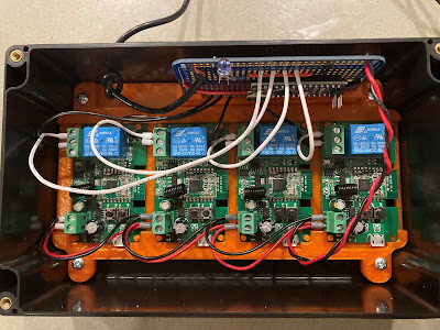
This outlines the directions on how to set up the offline television controller with Alexa. First, unscrew the top of the TV controller box, as shown below.  Next, ensure that your Alexa device is near by and that the Alexa application is open and ready for configuration.  Plug in the offline television device to power, the red lights on each relay should begin to flash. Immediately after plugging in the device to power, tell Alexa to "discover devices". While the devices are being discovered, you will hear each of the relays click and all of the red lights on the relays should go from flashing to solid red.  After Alexa is finished discovering devices, go into the Alexa app in the "Devices" section and then click on "Lights". There should be four new devices discovered under the light section as shown below.  Now, it needs to be determined which "Light" in the Alexa app corresponds to which relay in the device. To do this, toggle on each of the ...

Offline Alexa Nurse Call Device (2nd Generation)

Image
This document outlines the second-generation design for the offline Alexa nurse call system. This device requires no coding or soldering if following the steps listed below. This system allows Alexa to work offline to control most hospital call light systems that work off a 1/4" stereo plug input. For more information on how this system works, please refer to this blog post.  Listed below are all the parts required (with links): ZigBee Relay ¼” male to ¼” female mono stereo cable Project box 12V power supply   Steps for assembling device: Step 1: Take the ¼” male to ¼” female mono stereo cable and cut the wire to separate the male and female ends. It is best to cut the wire so the male end has 2/3 rds or more of total wire length (cut closer to the female end). Once the wire has been cut, strip the wires as shown in the figure below, so both the male and female ends have two bare wires each. Step 2: Take the 12V power supply and cut the barrel jack off th...

Wiring: Television Device

Image
This post outlines the wiring for the offline Amazon Alexa device for control of the television in inpatient hospital rooms. To see how this device is connected in the hospital rooms, refer to this  post .  This outlines the wiring for the offline television device using Amazon Alexa. The following design uses the parts listed in a previous  post , along with a custom 3-D printed holder for inside of the project box enclosure. The 5V (Blue Wires) and GND (White Wires) pins on the Texas Instrument board should be wired to the 5V and GND on the barrel jack input. Additionally, the 5V and GND pins on the Texas Instruments board should be wired to the 5V and GND pins on the Arduino to power the boards. The DI05 pin (Orange Wire) and DI04 pin (Yellow Wire) should be wired to the A4 and A5 pins on the Arduino, respectively. This will allow the Texas Instruments board and Arduino to communicate over I2C.  The IR LED (Red Wire) is wired to the positive pole (5V) of the barre...

Wiring: Nurse Call Device

Image
This post outlines the wiring of the Nurse Call device for offline control with Amazon Alexa. To see how this device is connected in the hospital rooms, refer to this post .  This outlines the wiring for the offline Nurse Call device using Amazon Alexa. The following design uses the parts listed in a previous post , along with a custom 3-D printed holder for inside of the project box enclosure. The two 1/4" mono jacks are wired in parallel. One is to be used as an input for a manual call light switch, and the other is to be used as an output for the call light system. One of the poles of the 1/4" mono jack is connected to the COM pin on the relay (Black Wire), and the other is connected to the NO pin (Red Wire).  The DI06 Pin on the Texas Instruments board is wired to the IN (input) pin on the relay (Green Wire) to trigger momentary closure. The 3.3V pin and GND pin on the Texas Instruments board are wired to the VCC pin (Red Wire) and GND pin (Black Wire) on the relay, respe...

Offline Alexa Devices: Inpatient Room Set Up

Image
This post outlines the set up of the offline Alexa devices in inpatient rooms. For more information on the design of the offline Alexa devices, see this post . The set up of these devices is based on implementation at Courage Kenny Rehabilitation Institute. This project was done in partnership with Courage Kenny and Cummins Inc.  Nurse Call Set Up The offline nurse call device needs to be connected to the call light system via a 1/4" male to male mono jack cord . One of the 1/4" stereo jacks on the call light device will be used for this. The additional 1/4" mono jack port is for a manual call light option, such as a sip-and-puff or tent switch. It is highly recommended that a secondary call light access method is connected for safety purposes, as voice access is only meant as an alternative option . The call light box should be secured against the wall. This can be accomplished using high strength Velcro. It is best to secure as close as possible to the call light syst...