Offline Alexa Environmental Control System for Inpatient Rehabilitation Facilities
About this Project:
Amazon Alexa devices are a very inexpensive and effective environmental control option. However, use of Alexa devices in hospital environments has been limited due to HIPPA compliance issues. Typically, Alexa devices are connected to Wi-Fi and they record all voice recordings in the cloud. Due to this, as longs as Alexa devices are connected to Wi-Fi, they are at risk of violating HIPPA regulations. The purpose of this project was to create a way that Alexa devices can be used in hospital rooms for control of the call light, television, and lights without use of Wi-Fi. This would enable Alexa devices to be used in inpatient rehabilitation centers for individuals with limited mobility for control of their environment while remaining HIPPA compliant.
 |
| Offline Alexa Call Light Device |
 |
| Offline Alexa Television Device |
How it works:
Amazon has a specific version of the Echo devices called the Echo Plus which contains an internal ZigBee hub. ZigBee is a smart home communication method that is local and is not dependent on Wi-Fi. The Echo Plus devices also have a special feature called Local Voice Control. This enables all ZigBee devices that are connected directly to the ZigBee hub in the Echo Plus to be voice controlled independent of Wi-Fi. Therefore, the voice commands for all the ZigBee devices connected to Alexa are stored locally in the Alexa system. Initially, the Alexa needs to be connected to Wi-Fi to set up an account with the device and initially pair the ZigBee devices. However, after the ZigBee devices are paired and have been given time to load into the Echo device, the system can be taken off Wi-Fi and the devices will still be able to be controlled using voice commands. Note that all other voice features of the Alexa will be unavailable once the system is disconnected from Wi-Fi, only the ZigBee devices will be available for voice control.
Our Solution:
Two ZigBee devices were developed for local control with Alexa in hospital rooms. One connects to the call light system and the other controls the television. Both devices can be connected directly to the ZigBee hub within the Echo Plus and therefore can take advantage of the Local Voice Control feature.
Credit: This project was done in collaboration with Courage Kenny Rehabilitation Institute and Cummins Inc.
ZigBee Call Light Device
Design Overview:
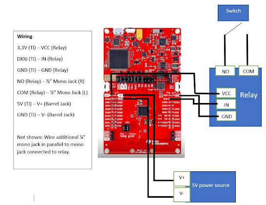
The ZigBee call light device consists of a Texas Instruments development board and a switch relay. The Texas Instruments device is programmed to communicate to the Echo Plus over ZigBee and control the switch relay upon providing the designated voice command on Alexa. The relay is programmed to close for a total of 1 second then re-open after the signal is sent from the Texas Instruments board. Therefore, the relay essentially activates as an "electronic switch" that can activate the call light. There is also an additional port for plugging in manual call light options such as a tent switch or sip-and-puff switch if needed.
Parts:
Texas Instruments LAUNCHXL-CC26X2R1 Board
Barrel Jack (If not connecting power supply directly to input)
Code:
Google Drive link to folder with call light code: Code
Download the .hex file code.
Assembly:
1) Download the zr_call_light.hex code for the Texas Instruments board and follow the directions below for loading it onto the board:
a) Install TI's UniFlash tool from: http://www.ti.com/tool/UNIFLASH
b) Launch UniFlash and plug in your CC26x2R dev board. UniFlash should auto recognize the board
c) Click the [Start] button below the board icon
d) Under Flash Image(s) on the Program tab click the [Browse] button
e) Select zr_call_light.hex
f) Click the [Load Image] button
2) After the Texas Instruments has the code uploaded, connect the board to Alexa. This can also be done following complete assembly of the device, but it is easier if it is done prior to wiring components. Note: make sure to turn off Amazon Sidewalk in the settings within the Alexa app, this may interfere with Local Voice Control working correctly.
a) Tell Alexa on the Echo Plus device that you want to pair to "discover devices"
b) Press button 1 on the Texas Instruments board. This button is on the side of the board and is labeled BTN-1. It is important that this step is done following the "discover devices" command to Alexa.
c) Once Alexa has completed discovering the device, it should appear as a light within the Alexa app. The name can now be changed to "Nurse Call" when editing the device. Though the name can be change to anything, names consisting of two words are typically understood best.
d) Let the Alexa device sit online connected to Wi-Fi for 24 hours to allow Alexa to load the commands locally to the device. Once it has sat online for 24 hours, it can be removed from the network and the commands will work offline with Alexa.
3) Assemble the board. The Image below shows a sketch of the wiring for the Texas Instruments board and relay. For step-by-step instructions for wiring the Offline Nurse Call device, refer to this post.
ZigBee Television Device
Design Overview:
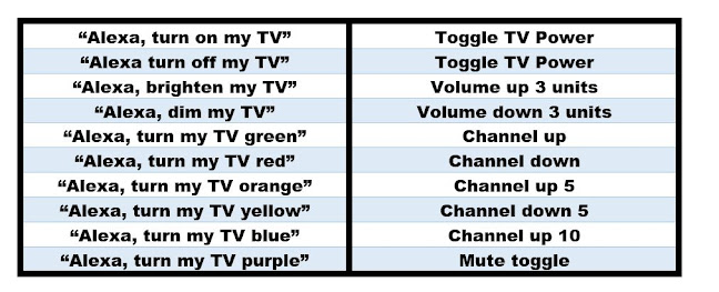
The ZigBee television device consists of a Texas Instruments development board and an Arduino Nano Every board. The Texas Instruments device communicates with the Echo Plus over ZigBee and receives commands upon a voice command to the Amazon Alexa. Once the command is received, another command is sent to the Arduino Nano, which transmits IR signals to the television. Alexa recognizes the Texas Instruments board as a color-changing dimmable light. This allows additional commands other than on and off to be sent. Therefore, color changing and dimmable commands can be assigned to IR commands for the television, in addition to on/off commands. The colors can be assigned to any infrared code. For instance, in the example code, the green color command corresponds to the channel up IR command for the TV and the red color command corresponds to channel down.
Parts:
Texas Instruments LAUNCHXL-CC26X2R1 Board
Code:
Google Drive link to folder with television code: Code
Download the .hex file code.
Assembly:
1) Download the zr_tv_remote.hex code for the Texas Instruments board and follow the directions below for loading it onto the board:
a) Install TI's UniFlash tool from: http://www.ti.com/tool/UNIFLASH
b) Launch UniFlash and plug in your CC26x2R dev board. UniFlash should auto recognize the board
c) Click the [Start] button below the board icon
d) Under Flash Image(s) on the Program tab click the [Browse] button
e) Select zr_tv_remote.hex
f) Click the [Load Image] button
2) After the Texas Instruments has the code uploaded, connect the board to Alexa. This can also be done following complete assembly of the device, but it is easier if it is done prior. Note: make sure to turn off Amazon Sidewalk in the settings within the Alexa app, this may interfere with Local Voice Control working correctly.
a) Tell Alexa on the Echo Plus device you want to pair to "discover devices"
b) Press button 1 on the Texas Instruments board. This button is on the side of the board and is labeled BTN-1. It is important that this step is done following the "discover devices" command to Alexa.
c) Once Alexa has completed discovering the device, it should appear as a light within the Alexa app. The name can now be changed to "My TV" when editing the device. The name can be change to anything, however names consisting of two words are typically understood best.
d) Let the Alexa device sit online connected to Wi-Fi for 24 hours to allow Alexa to load the commands locally to the device. Once it has sat online for 24 hours, it can be removed from the network and the commands will work offline with Alexa.
3) Program the Arduino Nano every with the code for sending the IR signals. Note that if you would like to change the IR signals in the code for a different TV model, the HEX TV codes can be found on this site: https://irdb.globalcache.com/.
a) Download library for Arduino Nano Every from Board Manager
b) Download IR library to Arduino Library folder: https://github.com/bengtmartensson/Infrared4Arduino
c) Download code for Arduino Nano provided in the Google Drive folder: i2c_ir_remote_LG1.ino
d) Load the code onto the Arduino Nano
4) Assemble the board. The Image below shows a sketch of the wiring for the Texas Instruments board and Arduino Nano Every. The same schematic is also available within the Google Drive folder as a PDF. Step-by-step directions can be referenced in this post.
Above is an image of the device wired using a breadboard. Note that no soldering was needed for connecting the device using this method. However, all connections can be soldered if desired. If going with the solderless approach with the mini breadboard, use 22 AWG solid core wire.


Comments
Post a Comment